Writing your own NES emulator Part 3 - the 6502 CPU
Emulating the NES 6502 CPU
It’s been a while since the last update - I was mostly focusing on database technologies. Beginning of the year 2021 is a bit slow (that’s when many big companies start their annual / semi-annual review process), so I had a bit of time to write up this post about 6502 CPU emulation. All the code referenced in this post is in my simple NES emulator github repo NesChan. It’s fun to go back and look at my old code and the 6502 CPU wiki.
The 6502 CPU
NES uses 8-bit 6502 CPU with 16-bit address bus, meaning it can access memory range 0x0000~0xffff - not much, but more than enough for games back in the 80s with charming dots and sprites. It is used in a surprising large range of famous vintage computers/consoles like Apple I, Apple II, Atari, Commodore 64, and of course NES. The variant used by NES is a stock 6502 without decimal mode support. It is running at 1.79HMZ (PAL version runs at 1.66MHZ). It has 3 general purpose register A/X/Y, and 3 special register P (status) /SP (stack pointer) /PC (program counter, or instruction pointer), all of them being 8-bit except PC which is 16-bit. NES dev wiki has a great section on 6502 CPU that has a lot more details and we’ll be covering the most important aspects in the remainder of the article.
To emulate the CPU, the main loop would look something like this:
- We start at a memory location by set current program counter (also known as instruction pointer in other architectures) PC to that location
- Check if we reached the special end condition (end of program, BRK instruction, infinite loop, etc…), if met, terminate the execution process
- Decode CPU instruction at current PC
- Set instruction pointer to next instruction
- Fetch data as per memory access mode
- Execute instruction with data fetched
- Move to the next instruction by going back to 2
The most interesting aspect are instruction decoding, memory access modes, and instruction execution. Let’s look at this one by one.
Decoding the instructions
Assembly instructions are usually encoded with 3 character memonics and they typically perform very low level hardware related operations supported by the CPU, to keep CPU simple and reduce cost. That’s why assembly instructions are considered low level. High-level language statements are usually compiled down to one or more CPU instructions, with the help of compiler. This is a perfect example of layering.
Let’s just take a look at a few examples of what 6502 CPU can do:
DEC,DEX,DEYfor decrementing memory, X register, Y register, respectivelyJMPfor jumping to a particular address to keep executing codeLDA,LDX,LDYfor loading A/X/Y register into target location, depending on the memory address modeADC,SBCfor addition / subtraction using the A register (accumulator) and specified memory location, so basically A += M and A-= M, taking carry flag into account as well
If you are interested to know more, you can go to this page for a list of common 6502 CPU instructions and what they do.
Before executing the instruction, you need to first look up the bytes in memory and understand which instruction it represents, what is the arguments, etc. This is called decoding. Fortunately, 6502 CPU instructions are always single byte, only the arguments differ by memory access mode. This makes the decoding much easier - we just need a big table of all instructions and then call the right helper function for that instruction based on the byte!
We’ll look at memory access mode later. For now you’ll just need to know they indicates where the actual data is coming from, while the instruction itself is the operation. Instruction typically supports different memory access modes so that it can operate on different data from different locations using different methods, whether it is register, memory, etc.
In order to build the table, it’s useful to visualize it by looking at the following table from nesdev unofficial opcodes wiki:
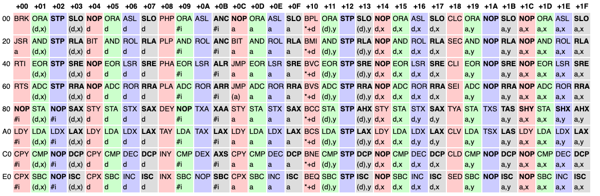
But in order to see the patterns a bit better, let’s re-arrange it:
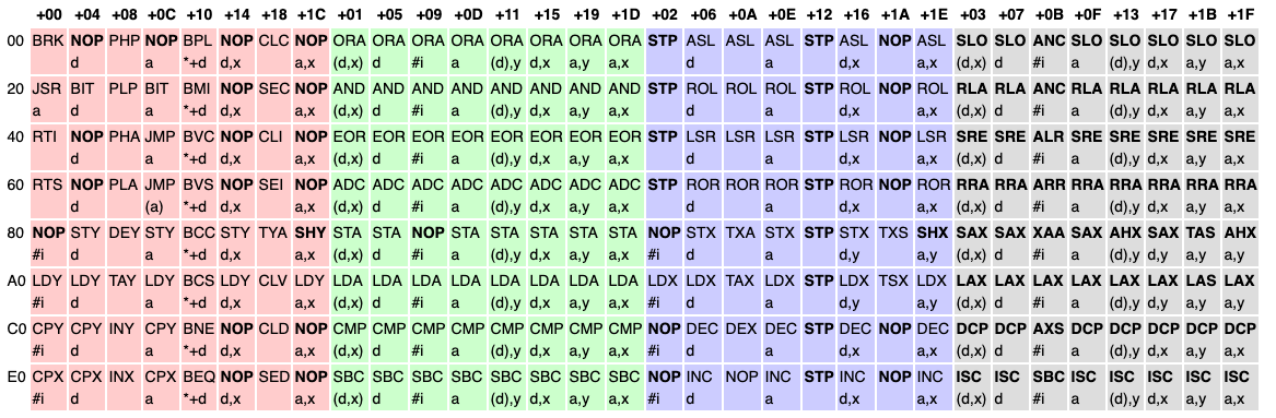
You can see the ALU (green ones, that does math operations) and the RMW (blue ones, = Read Modify Write) instructions follow a very clear pattern, while the red (mostly control instructions) and gray (unofficial / undocumented instructions) are sort of all over the place.
To keep things simple (and make modification easier, as I was still learning the instructions, and I don’t want to do it over when I misunderstood something), in the current implementation I went with a switch case approach with macros. This could be easily updated to use a real table with helper function pointers. You might think the jump table approach might be faster, but actually the reality can be a bit more complicated: compiler should easily create a jump table, and jumping into inlined version of the helper functions directly, end up being much faster than a jump table solution. Such optimization are actually more difficult with function pointers (but not impossible). Either way, since I’m not optimizing for a benchmark but to run NES games, I didn’t care too much about performance.
For example, for ALU instructions we use this macro in nes_cpu.cpp:
#define IS_ALU_OP_CODE_(op, offset, mode) \
    case nes_op_code::op##_base + offset : \
        NES_TRACE4(get_op_str(#op, nes_addr_mode::nes_addr_mode_##mode)); \
        op(nes_addr_mode::nes_addr_mode_##mode);  \
        break;
This defines a case statement for a variant of instruction op. For example, for ADC, offset 0x9 is ADC with immediate memory access mode. We’ll be calling to the op helper function for executing the code with the corresponding memory access mode. NES_TRACE4 is for logging and we can ignore that for now.
And for each particular ALU instruction, we define 8 variants of all memory access patterns based on the table earlier:
#define IS_ALU_OP_CODE(op) \
    IS_ALU_OP_CODE_(op, 0x9, imm) \
    IS_ALU_OP_CODE_(op, 0x5, zp) \
    IS_ALU_OP_CODE_(op, 0x15, zp_ind_x) \
    IS_ALU_OP_CODE_(op, 0xd, abs) \
    IS_ALU_OP_CODE_(op, 0x1d, abs_x) \
    IS_ALU_OP_CODE_(op, 0x19, abs_y) \
    IS_ALU_OP_CODE_(op, 0x1, ind_x) \
    IS_ALU_OP_CODE_(op, 0x11, ind_y)
For example, ADC + 0x9 is immediate mode, ADC + 0x5 is zero page mode, etc.
Then we can support a series of ALU instructions easily with these macros:
        IS_ALU_OP_CODE(ADC)
        IS_ALU_OP_CODE(AND)
        IS_ALU_OP_CODE(CMP)
        IS_ALU_OP_CODE(EOR)
        IS_ALU_OP_CODE(ORA)
        IS_ALU_OP_CODE(SBC)
Take a simple instruction as an example, the code looks like follows:
// Logical AND
void nes_cpu::AND(nes_addr_mode addr_mode)
{
    operand_t op = decode_operand(addr_mode);
    uint8_t val = read_operand(op);
    A() &= val;

    // flags
    calc_alu_flag(A());

    // cycle count
    step_cpu(get_cpu_cycle(op, addr_mode));
}
decode_operandis responsible for decoding the following bytes based on the address mode, and return the access pattern inoperand_t- Next we proceed to read the operand using
opintoval. The reason the decoding and reading are separate step is because some instruction do read, write, or both, so it is useful to separate them into different helpers. - Once we read the val, as per AND instruction, we
ANDthe accmulator A register withvaland then write it back. Note we have helpers that return registers (which really are just variables) as reference so the code reads quite naturally:
    uint8_t &A() { return _context.A; }
    uint8_t &X() { return _context.X; }
    uint8_t &Y() { return _context.Y; }
    uint16_t &PC() { return _context.PC; }
    uint8_t &P() { return _context.P; }
    uint8_t &S() { return _context.S; }
- Based on the result of A, we need to update the ALU zero/negative flags accordingly. Those flags are typically checked at beginning of instruction and updated at the end of instruction, usually for math operations (carry flag) or controls (jump if zero). For a full list flags you can refer to this list.
- Finally, we simulate the passing of CPU cycles (or rather, time). This is important for accuracy of emulation as many games rely this for timing, especially to synchronize with GPU cycles! Now that’s what we call real programmers .
Memory access mode
This is one of the more complicated aspect of 6502 CPU. Many instructions have different modes when it comes to where the operands are coming from. This is the full list of all suppported modes:
| Abbr | Name | Notes |
|---|---|---|
| Imp | Implicit | Instructions like RTS or CLC have no address operand, the destination of results are implied. |
| A | Accumulator | Many instructions can operate on the accumulator, e.g. LSR A. Some assemblers will treat no operand as an implicit A where applicable. |
| #v | Immediate | Uses the 8-bit operand itself as the value for the operation, rather than fetching a value from a memory address. |
| d | Zero page | Fetches the value from an 8-bit address on the zero page. |
| a | Absolute | Fetches the value from a 16-bit address anywhere in memory. |
| label | Relative | Branch instructions (e.g. BEQ, BCS) have a relative addressing mode that specifies an 8-bit signed offset relative to the current PC. |
| (a) | Indirect | The JMP instruction has a special indirect addressing mode that can jump to the address stored in a 16-bit pointer anywhere in memory. |
There are also more complicated memory access modes using the above:
| Abbr | Name | Formula | Cycles |
|---|---|---|---|
| d,x | Zero page indexed | val = PEEK((arg + X) % 256) | 4 |
| d,y | Zero page indexed | val = PEEK((arg + Y) % 256) | 4 |
| a,x | Absolute indexed | val = PEEK(arg + X) | 4+ |
| a,y | Absolute indexed | val = PEEK(arg + Y) | 4+ |
| (d,x) | Indexed indirect | val = PEEK(PEEK((arg + X) % 256) + PEEK((arg + X + 1) % 256) * 256) | 6 |
| (d),y | Indirect indexed | val = PEEK(PEEK(arg) + PEEK((arg + 1) % 256) * 256 + Y) | 5+ |
In the code I have a enum for all the supported modes:
// Addressing modes of 6502
// http://obelisk.me.uk/6502/addressing.html
// http://wiki.nesdev.com/w/index.php/CPU_addressing_modes
enum nes_addr_mode
{
    nes_addr_mode_imp,        // implicit
    nes_addr_mode_acc,        //          val = A
    nes_addr_mode_imm,        //          val = arg_8
    nes_addr_mode_ind_jmp,    //          val = peek16(arg_16), with JMP bug
    nes_addr_mode_rel,        //          val = arg_8, as offset
    nes_addr_mode_abs,        //          val = PEEK(arg_16), LSB then MSB
    nes_addr_mode_abs_jmp,    //          val = arg_16, LSB then MSB, direct jump address
    nes_addr_mode_zp,         //          val = PEEK(arg_8)
    nes_addr_mode_zp_ind_x,   // d, x     val = PEEK((arg_8 + X) % $FF ), 4 cycles
    nes_addr_mode_zp_ind_y,   // d, y     val = PEEK((arg_8 + Y) % $FF), 4 cycles
    nes_addr_mode_abs_x,      // a, x     val = PEEK(arg_16 + Y), 4+ cycles
    nes_addr_mode_abs_y,      // a, y     val = PEEK(arg_16 + Y), 4+ cycles
    nes_addr_mode_ind_x,      // (d, x)   val = PEEK(PEEK((arg + X) % $FF) + PEEK((arg + X + 1) % $FF) * $FF), 6 cycles
    nes_addr_mode_ind_y,      // (d), y   val = PEEK(PEEK(arg) + PEEK((arg + 1) % $FF)* $FF + Y), 5+ cycles
};
Recall that in instruction implementation we call decode_operand and read_operand (there is also write_operand) to decode and then read the target (whether it is register, an address, etc). So all the magic for decoding memory address modes are in there.
For example, following code in decode_operand_addr (used in decode_operand internally supports indirect y mode:
        else if (addr_mode == nes_addr_mode::nes_addr_mode_ind_y)
        {
            // Indirect Indexed
            // implies a table of table address in zero page
            uint8_t arg_addr = decode_byte();
            uint16_t addr = peek(arg_addr) + (uint16_t(peek((arg_addr + 1) & 0xff)) << 8);
            uint16_t new_addr = addr + _context.Y;
            return new_addr;
        }
Show me the RAM
Accesing “RAM” in a emulator in theory should be easy, right? Just reserve a “big chunk” of whopping 64K RAM and access that. Unfortunately it is a little bit more complicated than that:
- The system only has built-in 2KB RAM - RAM is expensive those days
- Some memory are mapped to I/O (such as PPU) registers so accessing those registers become simple memory operations, rather than, say, dedicated instructions
- When NES cartridges are inserted, its onboard data (RAM, ROM) are mapped onto the 64K memory space as well
So the actual memory layout looks like this:
| Address range | Size | Device |
|---|---|---|
| $0000-$07FF | $0800 | 2KB internal RAM |
| $0800-$0FFF | $0800 | Mirrors of $0000-$07FF |
| $1000-$17FF | $0800 | Mirrors of $0000-$07FF |
| $1800-$1FFF | $0800 | Mirrors of $0000-$07FF |
| $2000-$2007 | $0008 | NES PPU registers |
| $2008-$3FFF | $1FF8 | Mirrors of $2000-2007 (repeats every 8 bytes) |
| $4000-$4017 | $0018 | NES APU and I/O registers |
| $4018-$401F | $0008 | APU and I/O functionality that is normally disabled. See CPU Test Mode. |
| $4020-$FFFF | $BFE0 | Cartridge space: PRG ROM, PRG RAM, and mapper registers (See Note) |
For more details you can refer to this page in NES wiki.
Dealing with cartridges and mappers are another big topic and a whole lot of complexity which we’ll cover a bit later. For now we’ll treat it as a black box.
All these means that whenever you write to a byte you need to do a bit of indirection (just like most of magic in computer science):
void nes_memory::set_byte(uint16_t addr, uint8_t val)
{
    redirect_addr(addr);
    if (is_io_reg(addr))
    {
        write_io_reg(addr, val);
        return;
    }

    if (_mapper && (_mapper_info.flags & nes_mapper_flags_has_registers))
    {
        if (addr >= _mapper_info.reg_start && addr <= _mapper_info.reg_end)
        {
            _mapper->write_reg(addr, val);
            return;
        }
    }

    _ram[addr] = val;
}
Testing
I use doctest which is a simple and convenient testing framework that is good enough for my needs. At the beginning I write manual tests - basically execute a bunch of instructions until BRK (stop the system) and verify the state of the CPU and RAM:
TEST_CASE("CPU tests") {
    nes_system system;

    SUBCASE("simple") {
        INIT_TRACE("neschan.instrtest.simple.log");

        cout << "Running [CPU][simple]..." << endl;

        system.power_on();

        system.run_program(
            {
                0xa9, 0x10,     // LDA #$10     -> A = #$10
                0x85, 0x20,     // STA $20      -> $20 = #$10
                0xa9, 0x01,     // LDA #$1      -> A = #$1
                0x65, 0x20,     // ADC $20      -> A = #$11
                0x85, 0x21,     // STA $21      -> $21=#$11
                0xe6, 0x21,     // INC $21      -> $21=#$12
                0xa4, 0x21,     // LDY $21      -> Y=#$12
                0xc8,           // INY          -> Y=#$13
                0x00,           // BRK
            },
            0x1000);

        auto cpu = system.cpu();

        CHECK(cpu->peek(0x20) == 0x10);
        CHECK(cpu->peek(0x21) == 0x12);
        CHECK(cpu->A() == 0x11);
        CHECK(cpu->Y() == 0x13);
    }
But this quickly get tedious. Fortunately, there are a lot of existing test roms. I’m been using this one - it is fairly comprehensive. This does mean I need to implement a rudimentary ROM loading first (which we won’t cover here), but once that’s ready I can just load the ROM and follow the convention of the test ROM - in this case it means checking peek(0x6000) == 0.
#define INSTR_V5_TEST_CASE(test) \
    SUBCASE("instr_test-v5 " test) { \
        INIT_TRACE("neschan.instrtest.instr_test-v5." test ".log"); \
        cout << "Running [CPU][instr_test-v5-" << test << "]" << endl; \
        system.power_on(); \
        auto cpu = system.cpu(); \
        cpu->stop_at_infinite_loop(); \
        system.run_rom("./roms/instr_test-v5/rom_singles/" test ".nes", nes_rom_exec_mode_reset); \
        CHECK(cpu->peek(0x6000) == 0); \
    }
With that I can run a bunch of ROMs as regression tests, much better:
    INSTR_V5_TEST_CASE("01-basics")
    INSTR_V5_TEST_CASE("02-implied")
    // INSTR_V5_TEST_CASE("03-immediate")
    INSTR_V5_TEST_CASE("04-zero_page")
    INSTR_V5_TEST_CASE("05-zp_xy")
    INSTR_V5_TEST_CASE("06-absolute")
    // INSTR_V5_TEST_CASE("07-abs_xy")
    INSTR_V5_TEST_CASE("08-ind_x")
    INSTR_V5_TEST_CASE("09-ind_y")
    INSTR_V5_TEST_CASE("10-branches")
    INSTR_V5_TEST_CASE("11-stack")
    INSTR_V5_TEST_CASE("12-jmp_jsr")
    INSTR_V5_TEST_CASE("13-rts")
    INSTR_V5_TEST_CASE("14-rti")
    // INSTR_V5_TEST_CASE("15-brk")
    // INSTR_V5_TEST_CASE("16-special")
}
Some of the commenting are most likely signs there are still bugs in CPU emulation.
Conclusion
It took me a few days to implement all CPU and get majority of the CPU tests to pass. Things are a bit more subtle than I expected, but that’s probably the case for emulating real world CPU which always has its own quirks or even bugs, and the documentation has bugs too (which are hard to find unless you test with a real CPU or a emulator). There are quite a bit of subtle behavior I didn’t cover (such as page crossing, etc) that I need to get exactly right. Getting CPU emulation correct is absolutely critical for getting games working, not surprisingly. One thing that did surprise me is that the last bug that prevented Super Mario Bros from working is bugs in my CPU emulation, including a documentation bug. If I remember correctly I had to debug it with another emulator side by side to find out the exact problem. On retrospective I probably should’ve get all the CPU tests working properly, and the fact that I had disabled a few (especially the earlier ones from 1-14) is definitely red flag. Unfortunately I was too excited to push ahead and “mostly working” is deemed “good enough”, which turned out to be a big mistake. That’s why we work on side projects - have fun, and learn something doing it.
The series so far…
If you are hungry for more NES…
Head to NESDev Wiki - I’ve learned pretty much everything about NES there. There is also a great book on NES called I am error, which is surprisingly deeply technical for a book about history of NES.